Ignition Control Module: Testing and Inspection
IGNITION COIL AND IGNITION POWER TRANSISTORRequired Special Tool:
- MB991658: Test Harness
Measurement Method
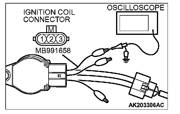
1. Disconnect the ignition coil connector, and connect test harness special tool (MB991658) between the separated connector. (All terminals should be connected.)
2. Connect the oscilloscope probe to ignition coil connector terminal No. 3.
Alternate method (Test harness not available)
1. Connect the oscilloscope probe to ECM
2. Connect the oscilloscope probe to ECM
3. Connect the oscilloscope probe to ECM
4. Connect the oscilloscope probe to ECM
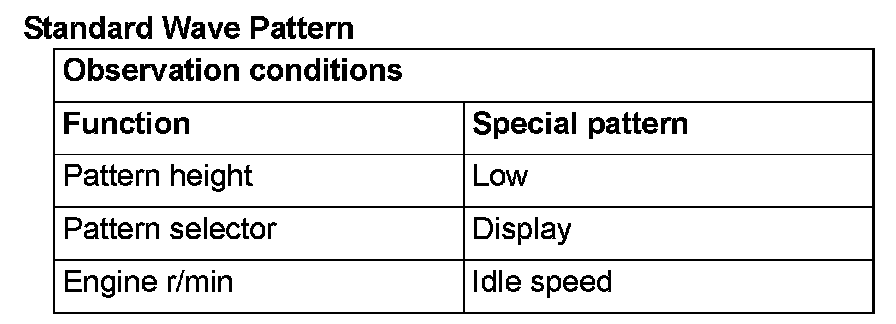
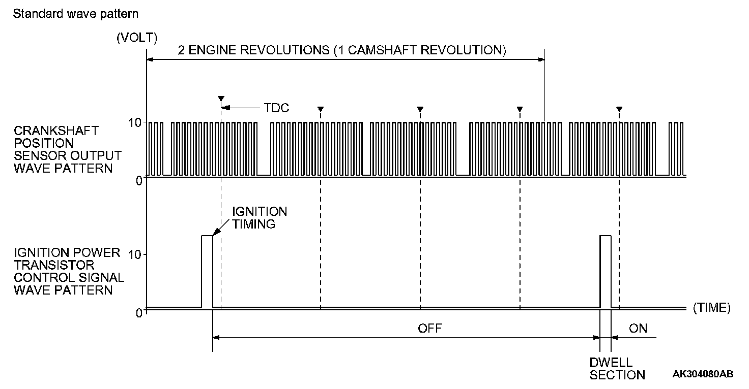
Standard Wave Pattern
Wave Pattern Observation Points
Point: The power transistor control signal (ignition timing) is advanced when the engine speed is increased.
Examples of Abnormal Wave Patterns
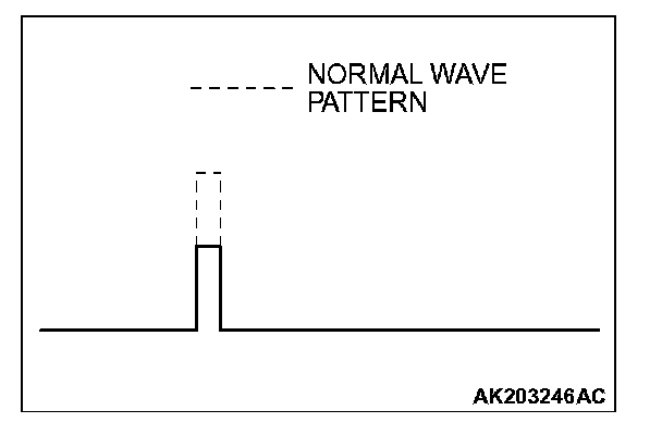
Example 1 (Wave pattern during engine cranking)
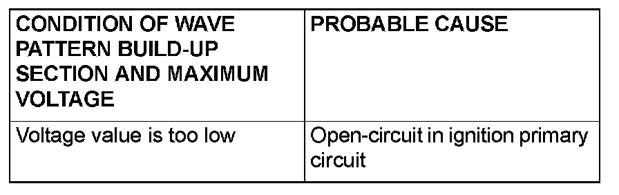
- Cause of problem
Open-circuit in ignition primary circuit
- Wave pattern characteristics
Voltage value is too low.