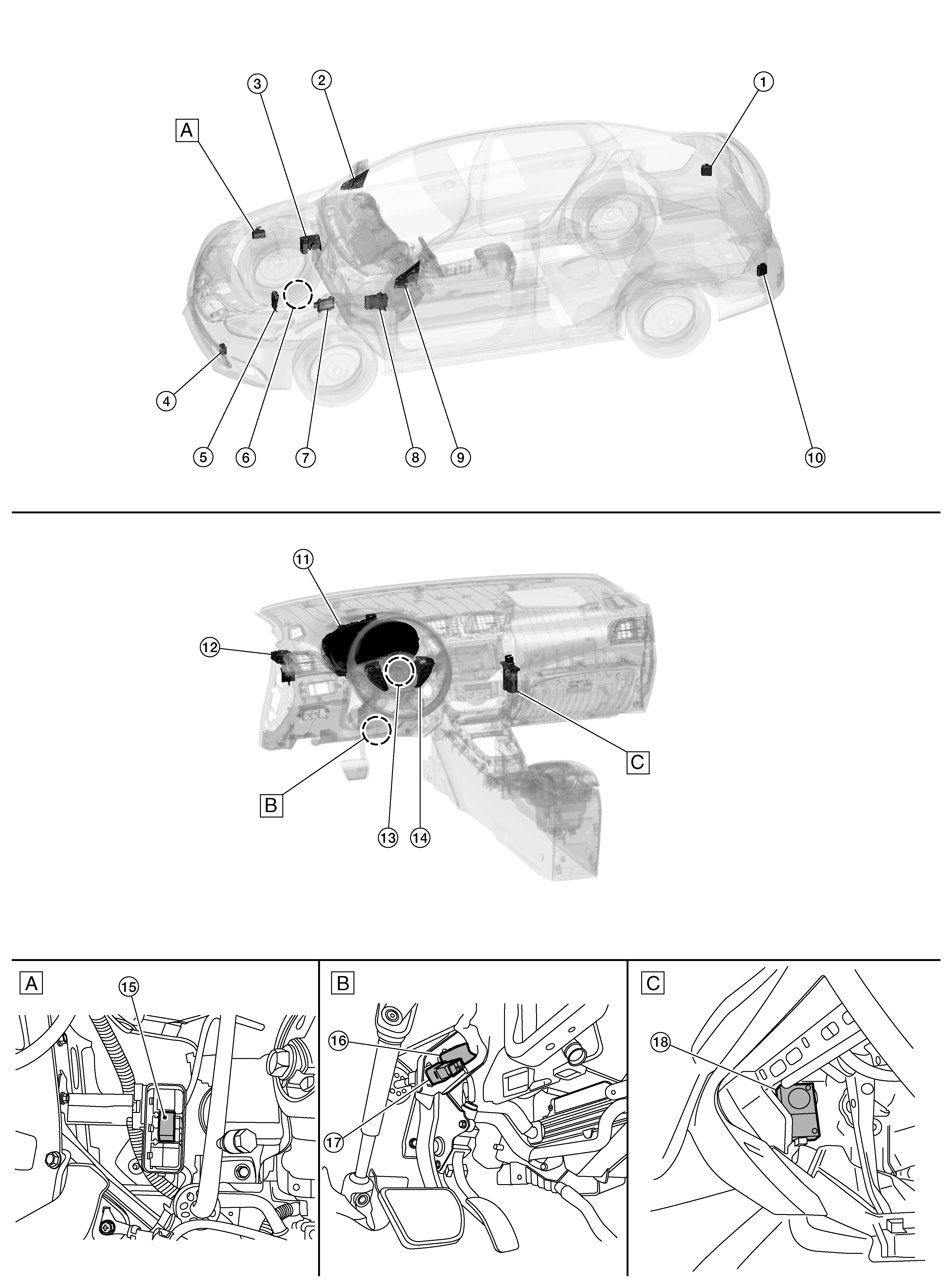
Component Location
WARNING: This page is about a different car, the 2017 Nissan Sentra. However, it is still accessible from the selected car via links, so may be relevant.
 Courtesy of NISSAN NORTH AMERICA, INC. Courtesy of NISSAN NORTH AMERICA, INC.
|
| A. |
View of ICC brake hold relay box |
B. |
View of brake pedal assembly |
C. |
View with glove box assembly removed |
| No. |
Component |
Description |
| 1. |
Side radar RH |
Refer to SIDE RADAR LH/RH . |
| 2. |
Blind Spot Warning indicator RH |
Refer to BLIND SPOT WARNING INDICATOR LH/RH . |
| 3. |
ABS actuator and electric unit (control unit) |
- ABS actuator and electric unit (control unit) transmits the vehicle speed signal (wheel speed), stop lamp signal and VDC/TCS/ABS system operation condition to ADAS control unit via CAN communication.
- ABS actuator and electric unit (control unit) controls the brake, based on a brake fluid pressure control signal received from ADAS control unit via CAN communication.
- Refer to COMPONENT LOCATION
for detailed installation location.
|
| 4. |
ICC sensor |
Refer to ICC SENSOR . |
| 5. |
TCM |
- TCM transmits the signal related to CVT control to ADAS control unit.
- Refer to COMPONENT LOCATION
for detailed installation location.
|
| 6. |
Park/Neutral position (PNP) switch (Back-up)
(with 6MT) |
- Transmits the reverse signal to ADAS control unit.
- Refer to COMPONENT LOCATION
for detailed installation location.
|
| 7. |
ECM |
- Transmits the ICC brake switch signal, stop lamp switch signal, ICC steering switch signal, etc., to ADAS control unit via CAN communication.
- Refer to COMPONENT LOCATION
for detailed installation location.
|
| 8. |
BCM |
- Transmits the turn indicator signal and position light request signal to ADAS control unit via CAN communication.
- Refer to COMPONENT LOCATION
for detailed installation location.
|
| 9. |
Blind Spot Warning indicator LH |
Refer to BLIND SPOT WARNING INDICATOR LH/RH . |
| 10. |
Side radar LH |
Refer to SIDE RADAR LH/RH . |
| 11. |
Combination meter |
|
| 12. |
ADAS control unit |
- ADAS control unit controls each system (ICC/FEB/BSW/RCTA), based on ITS communication signals and CAN communication signals from each control unit.
- ADAS control unit transmits engine torque command value, brake fluid pressure control signal, and buzzer output signal to each unit.
|
| 13. |
Steering angle sensor |
- Measures the rotation amount, rotation speed, and rotation direction of steering wheel and then transmits them to ADAS control unit via CAN communication.
- Refer to COMPONENT LOCATION
for detailed installation location.
|
| 14. |
ICC steering switch |
Refer to ICC STEERING SWITCH . |
| 15. |
ICC brake hold relay |
Refer to ICC BRAKE HOLD RELAY . |
| 16. |
Stop lamp switch |
Refer to BRAKE PEDAL POSITION SWITCH / STOP LAMP SWITCH . |
| 17. |
Brake pedal position switch |
| 18. |
Warning buzzer |
Refer to WARNING BUZZER . |