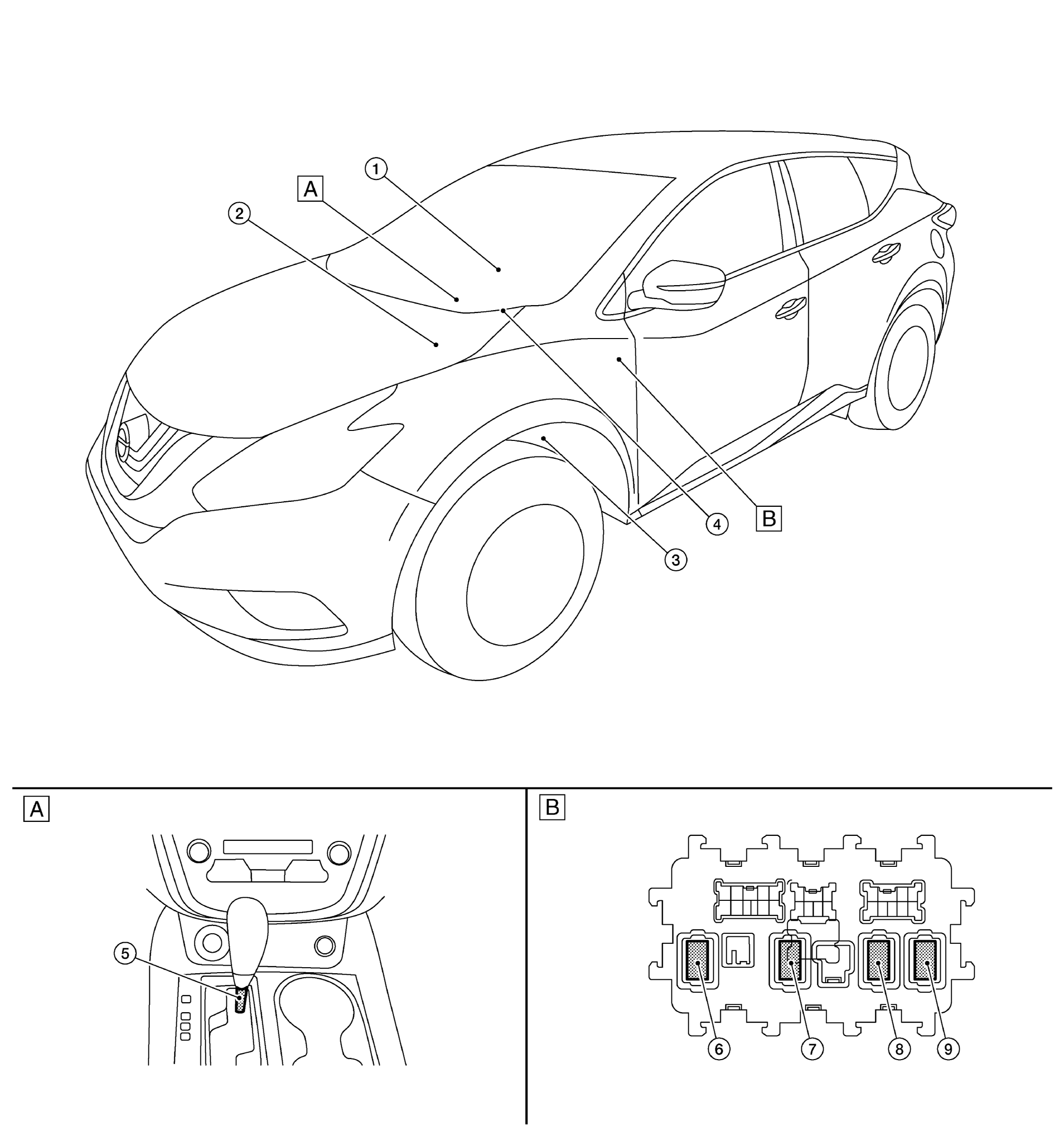
Component Location
WARNING: This page is about a different car, the 2017 Nissan Murano. However, it is still accessible from the selected car via links, so may be relevant.
 Courtesy of NISSAN NORTH AMERICA, INC. Courtesy of NISSAN NORTH AMERICA, INC.
|
| A. |
Front of center console |
B. |
Instrument lower panel LH |
| |
|
|
|
| No. |
Component |
Function |
| 1. |
Push-button ignition switch |
Refer to PUSH-BUTTON IGNITION SWITCH . |
| 2. |
IPDM E/R |
- IPDM E/R detects push-button ignition switch (push switch) status, and transmits push-button ignition switch status signal (CAN) to BCM.
- IPDM E/R receives ignition relay (IPDM E/R) control signal and ignition switch ON signal (CAN) from BCM, and controls ignition relay (built in IPDM E/R)
Refer to COMPONENT LOCATION
for detailed installation location. |
| 3. |
BCM |
- BCM controls power distribution system.
- BCM judges ignition switch position by push-button ignition switch (push switch) and vehicle condition.
- BCM checks the ignition switch position internally.
Refer to COMPONENT LOCATION
for detailed installation location. |
| 4. |
Stop lamp switch |
Stop lamp switch detects that brake pedal is depressed, and transmits the signal to BCM.
Refer to STOP LAMP SWITCH
. |
| 5. |
CVT shift selector |
CVT shift selector detects shift lever status, transmits detention switch signal to BCM.
Refer to COMPONENT LOCATION
for detailed installation location. |
| 6. |
Ignition relay-2 (in fuse block) |
- Ignition relay-2 is controlled by BCM.
- Ignition relay-2 supplies ignition ON power supply or ignition ON signal to each ECU and system when ignition is turned ON.
- BCM compares status of ignition relay-2 control signal and ignition position judged by BCM.
- BCM monitors ignition relay-2 operating status by ignition relay-2 feedback signal.
|
| 7. |
Front blower motor relay (in fuse block) |
- Front blower motor relay is controlled by BCM.
- Front blower motor supplies ignition ON power supply or ignition ON signal to air conditioning system when ignition is turned ON.
- BCM compares status of front blower motor relay control signal and ignition position judged by BCM.
|
| 8. |
Accessory relay-1 (in fuse block) |
- Accessory relay-1 is controlled by BCM.
- Accessory relay-1 supplies accessory power supply or ignition ON signal to each ECU when ignition is turned ON.
- BCM compares status of accessory relay-1 control signal, and ignition position judged by BCM.
|
| 9. |
Rear window defogger relay (in fuse block) |
Refer to COMPONENT LOCATION
. |