System Description
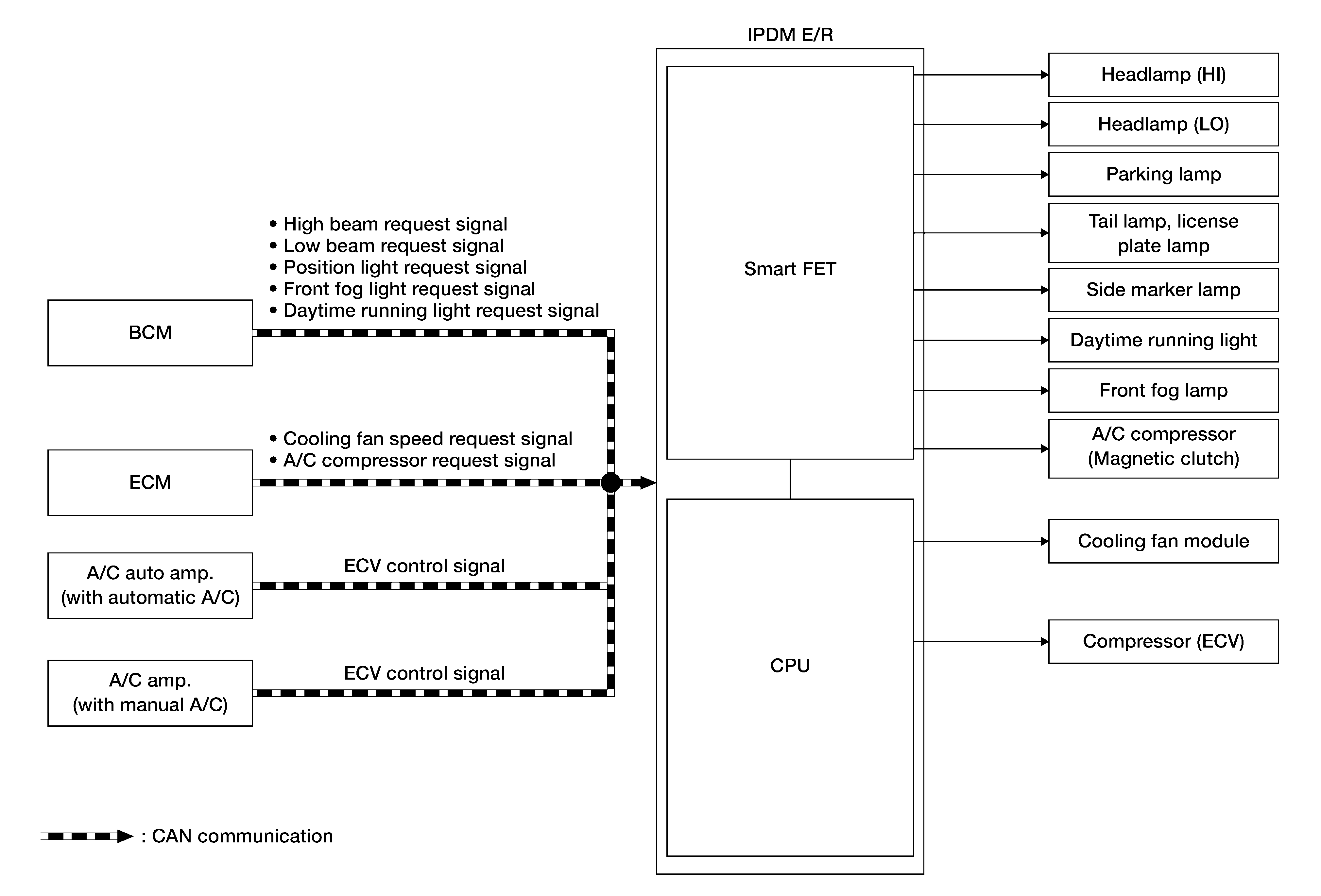
SYSTEM DIAGRAM
 Courtesy of NISSAN Courtesy of NISSAN
|
Description
| Component |
Function |
| Smart FET |
Refer to Component Description . |
| Headlamp (HI) |
The IPDM E/R supplies power supply voltage to each lamp, and turns the each lamp ON. |
| Headlamp (LO) |
| Parking lamp |
| Tail lamp, license plate lamp |
| Daytime running light |
| Front fog lamp |
| A/C compressor (magnetic clutch) |
The IPDM E/R supplies power supply voltage to the A/C compressor (magnetic clutch), and turns the magnet clutch ON. |
| Cooling fan module |
The IPDM E/R controls each actuator. |
| Compressor (ECV) |
INPUT SIGNAL AND OUTPUT SIGNAL
Major signal transmission between each unit via communication lines is shown in the following table:
| Component parts |
Signal description |
| BCM |
The BCM transmits the ON/OFF request signal for each lamp to IPDM E/R via CAN communication. |
| ECM |
- The ECM calculates the cooling level, and transmits the cooling fan speed request signal to the IPDM E/R via CAN communication.
- The ECM transmits the A/C compressor request signal to the IPDM E/R via CAN communication according to the status of the engine and refrigerant pressure.
|
| A/C auto amp. 1 |
The A/C auto amp. 1 or A/C amp. 2 transmits the ECV control signal to the IPDM E/R via CAN communication. |
| A/C amp. 2 |
| IPDM E/R |
- The IPDM E/R controls the Smart FET to control each lamp according to the control signal status of each lamp received from the BCM via CAN communication. Refer to the following:
- The IPDM E/R controls the Smart FET to control the A/C compressor (magnetic clutch) according to the A/C compressor request signal received from the ECM via CAN communication. Refer to System Description
(automatic A/C) or System Description
(manual A/C).
- The IPDM E/R controls the cooling fan module according to the cooling fan speed request signal received from the ECM via CAN communication. Refer to System Description
.
- The IPDM E/R controls the ECV (Electrical Control Valve) according to the ECV control signal received from the A/C auto amp. 1 or A/C amp. 2 via CAN communication. Refer to System Description
(automatic A/C) or System Description
(manual A/C).
|
1: Automatic A/C
2: Manual A/C