DME Connector Assignment
DME Connector Assignment
Note: The DME control module has 134 terminals which are divided between five connectors.
Connector I (9-pole):
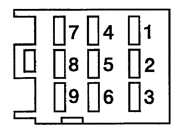
Connector I (9-pole)
1 - Terminal 15
2 - not assigned
3 - W-wire
4 - Ground, electronic system
5 - Ground, fuel injectors
6 - Ground, output stages
7 - Terminal 30
8 - DME relay (terminal 87)
9 - not assigned
Connector II (24-pole):
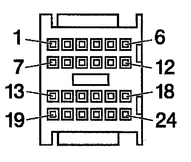
Connector II (24-pole)
1 - Oxygen sensor heating 2 after TWC
2 - not assigned
3 - CAN low (Tiptronic)
4 - CAN high (Tiptronic)
5 - not assigned
6 - not assigned
7 - Oxygen sensor heating 1 after TWC
8 - Ground, oxygen sensor 2 after TWC
9 - Ground, oxygen sensor 1 ahead of TWC
10 - Ground, oxygen sensor 2 ahead of TWC
11 - Ground, oxygen sensor 1 after TWC
12 - Automatic I/M test
13 - Oxygen sensor heating 2 ahead of TWC
14 - Signal, oxygen sensor 2 after TWC
15 - Signal, oxygen sensor 1 ahead of TWC
16 - Signal, oxygen sensor 2 ahead of TWC
17 - Signal, oxygen sensor 1 after TWC
18 - Triggering of A/C compressor relay (terminal 85)
19 - Oxygen sensor heating 1 ahead of TWC
20 - Triggering of engine compartment fan (terminal 85)
21 - Engine compartment temperature sensor
22 - 5-volt supply for mass air flow sensor
23 - Triggering of DME relay (terminal 85)
24 - not assigned
Connector III (52-pole):
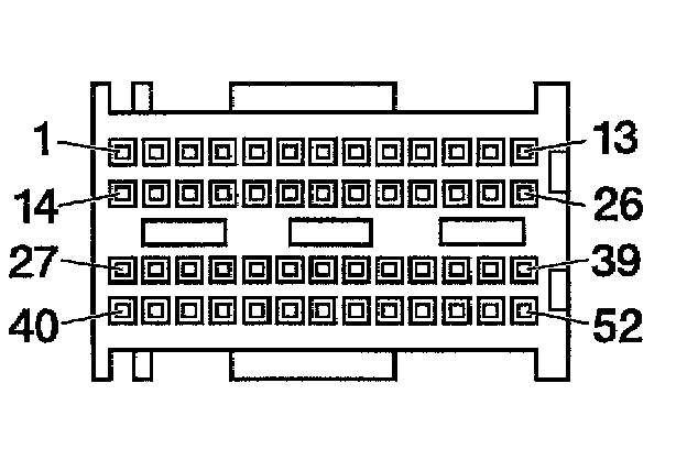
Connector III (52-pole)
1 - Knocking signal
2 - Fuel injector, cyl. 5
3 - EVAP canister purge valve
4 - Variable-length manifold
5 - Oil temperature sensor
6 - not assigned
7 - 5-volt supply for camshaft position sensor and differential pressure sensor
8 - Signal, throttle position sensor 2
9 - Ground, mass air flow sensor
10 - 5-volt supply for throttle actuation
11 - Triggering of secondary air pump relay (terminal 85)
12 - not assigned
13 - Start enable, Tiptronic (P + N)
14 - Pilot light, engine compartment fan
15 - Fuel injector, cy. 3
16 - not assigned
17 - Ground, sensors
18 - not assigned
19 - Signal, camshaft position sensor 2
20 - Signal, camshaft position sensor 1
21 - not assigned
22 - Engine coolant temperature sensor
23 - Signal, mass air flow sensor
24 - Signal, throttle position sensor 1
25 - Ground, throttle position sensors 1 + 2
26 - not assigned
27 - Fuel injector, cyl. 4
28 - Fuel injector, cyl. 6
29 - not assigned
30 - Secondary air valve
31 - not assigned
32 - Signal A, speed sensor
33 - not assigned
34 - Intake air temperature sensor
35 - not assigned
36 - Input, knock sensor 2
37 - Ground, knock sensor 2
38 - not assigned
39 - not assigned
40 - Fuel injector cyl. 2
41 - Fuel injector, cyl. 1
42 - Throttle motor actuator
43 - Throttle motor actuator
44 - not assigned
45 - Shield, speed sensor
46 - Signal B, speed sensor
47 - not assigned
48 - not assigned
49 - Input, knock sensor 1
50 - Ground, knock sensor 1
51 - not assigned
52 - not assigned
Connector IV (40-pole):
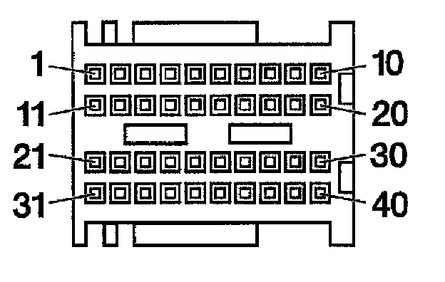
Connector IV (40-pole)
1 - Interlock clutch switch
2 - not assigned
3 - not assigned
4 - Coolant fan, stage 1
5 - Variant coding (ground for Tiptronic)
6 - A/C compressor requirement
7 - Ground, pedal sensor 1
8 - Signal, pedal sensor 1
9 - 5-volt supply for pedal sensor 1
10 - Triggering of fuel pump relay (terminal 85)
11 - Dim information from instrument cluster
12 - Ground, pedal sensor 2
13 - Signal, pedal sensor 2
14 - 5-volt supply for pedal sensor 2
15 - Ground, differential pressure sensor
16 - Crash signal (airbag)
17 - Speed signal output
18 - Cruise control pilot light
19 - Cruise control switch "Off"
20 - Coolant fan, stage 2
21 - Signal, differential pressure sensor
22 - Speed signal from ABS control module
23 - Cruise control clutch switch
24 - Stop light switch 1
25 - Cruise control switch "Set"
26 - not assigned
27 - Cruise control switch "Resume"
28 - Stop light switch 2
29 - not assigned
30 - EVAP canister shutoff valve
31 - Check Engine MIL
32 - not assigned
33 - Fuel gauge
34 - Fuel reserve pilot light
35 - not assigned
36 - CAN high (PSM)
37 - CAN low (PSM)
38 - not assigned
39 - Medium pressure switch (A/C)
40 - Start-inhibit relay (terminal 85)
Connector V (9-pole):
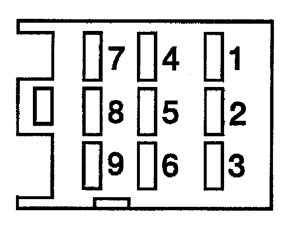
Connector V (9-pole)
1 Camshaft adjustment, bank 1
2 - Ignition coil, cyl. 4 (terminal 1)
3 - Camshaft adjustment, bank 2
4 - Ignition coil, cyl. 6 (terminal 1)
5 - Ground
6 - Ignition coil, cyl. 1 (terminal 1)
7 - Ignition coil, cyl. 3 (terminal 1)
8 - Ignition coil, cyl. 2 (terminal 1)
9 - Ignition coil, cyl. 5 (terminal 1)