LEMON Manuals: Even more car manuals for everyone: 1960-2025
Home >> Subaru >> 2006 >> Forester XT Limited, Automatic >> Repair and Diagnosis >> Engine Performance >> Engine Control Systems >> Fuel Injection (Fuel Systems) (H4DOTC) >> Intake Manifold >> Disassembly
April 5, 2026: LEMON Manuals is launched! Read the announcement.

Intake Manifold: Disassembly

  1. Remove the fuel pipe protector RH.
    Fig 1: Locating Fuel Pipe Protector With Bolts (RH)
    G04998298
  2. Remove the fuel pipe protector LH.
    Fig 2: Locating Fuel Pipe Protector With Bolts (LH)
    G04998299
  3. Remove the engine ground terminal from the intake manifold.
    Fig 3: Locating Engine Ground Terminal On Intake Manifold
    G04998300
    Fig 4: Locating Engine Ground Terminal On Intake Manifold
    G04998301
  4. Disconnect the connector from the throttle position sensor (A), and the manifold pressure sensor (B).
    Fig 5: Identifying Throttle Position And Manifold Absolute Pressure Sensor
    G04998253
  5. Remove the throttle body to intake manifold.
    Fig 6: Locating Bolts Securing Throttle Body To Intake Manifold
    G04998255
  6. Disconnect the connector from fuel injector.
    Fig 7: Locating Fuel Injector Connectors
    G04998304
  7. Disconnect the connector from tumble generator valve actuator.
    Fig 8: Locating Tumble Generator Valve Actuator Connector
    G04998305
  8. Disconnect the connector from tumble generator valve sensor.
    Fig 9: Locating Tumble Generator Valve Sensor Connector
    G04998306
  9. Disconnect the connector from purge control solenoid valve.
  10. Remove the purge control solenoid valve.
    Fig 10: Locating Purge Control Solenoid Valve Connector
    G04998307
  11. Disconnect the evaporation hose and purge valve from the intake manifold.
    Fig 11: Identifying Evaporation Hose And Purge Valve On Intake Manifold
    G04998308
  12. Remove the two bolts which hold fuel pipes on the left side of intake manifold.
    Fig 12: Locating Bolts Holding Fuel Pipes On Left Side Of Intake Manifold
    G04998309
  13. Remove the bolt which holds fuel injector pipe onto intake manifold.
    • LH side
    Fig 13: Locating Bolt Holding Fuel Injector Pipe Onto Intake Manifold (LH)
    G04998310
    Fig 14: Locating Bolt Holding Fuel Injector Pipe Onto Intake Manifold (LH)
    G04998311
    • RH side
    Fig 15: Locating Bolt Holding Fuel Injector Pipe Onto Intake Manifold (RH)
    G04998312
    Fig 16: Locating Bolt Holding Fuel Injector Pipe Onto Intake Manifold (RH)
    G04998313
  14. Remove the fuel injector.
    Fig 17: Placing Fuel Injector
    G04998314
  15. Remove the harness bracket which holds the engine harness onto intake manifold.
    Fig 18: Locating Harness Bracket
    G04998315
  16. Remove the engine harness from intake manifold.
  17. Loosen the clamp which holds the front LH side fuel hose to injector pipe to remove the pipe from clamp.
    Fig 19: Locating Fuel Hose Clamp
    G04998316
  18. Loosen the clamp which holds the RH side fuel hose to injector pipe to remove the pipe from clamp.
    Fig 20: Locating Clamp Holding Fuel Hose To Fuel Injector Pipe (RH)
    G04998317
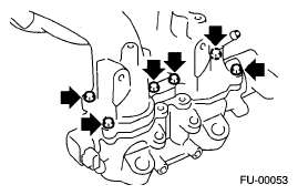
  19. Remove the bolts which install fuel pipes on intake manifold.
    Fig 21: Locating Bolts Installing Fuel Pipe Assembly On Intake Manifold
    G04998318
  20. Remove the fuel pipe assembly and pressure regulator from intake manifold.
  21. Remove the intake duct from intake manifold.
    Fig 22: Locating Intake Duct
    G04998319
  22. Remove the tumble generator assembly from intake manifold.
Fig 23: Locating Tumble Generator Valve Assembly Bolts
G04998320