System Diagram
WARNING: This page is about a different car, the 2013 Toyota Camry. However, it is still accessible from the selected car via links, so may be relevant.
 Courtesy of © TOYOTA, LICENSE AGREEMENT TMS1002
 Courtesy of © TOYOTA, LICENSE AGREEMENT TMS1002
 Courtesy of © TOYOTA, LICENSE AGREEMENT TMS1002
| Component |
Outline |
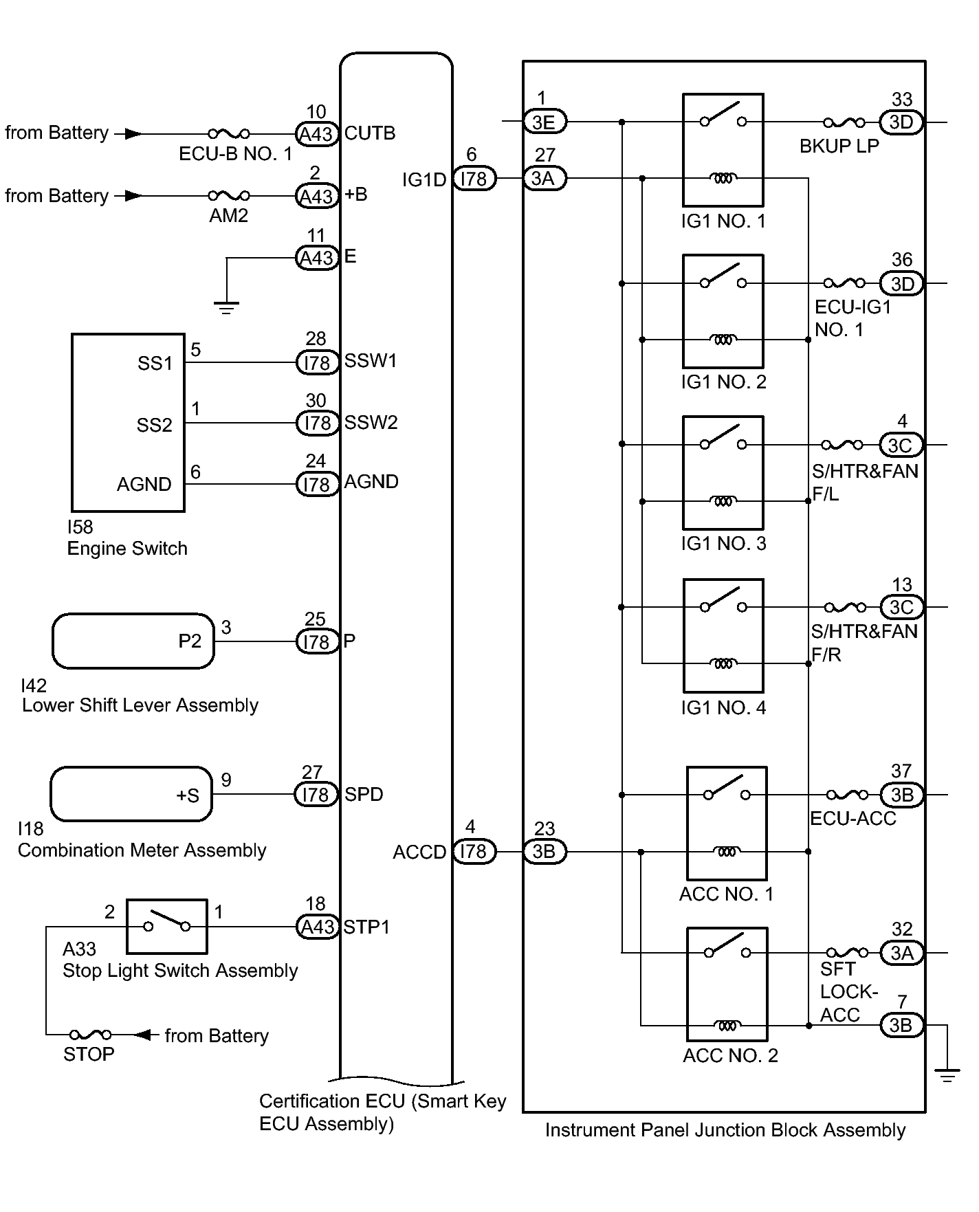
Engine switch
- Transponder key amplifier
|
- Turns on the power and starts the engine.
- Contains a built-in transponder key amplifier to start the engine when the key does not operate properly due to a depleted battery or wave interference.
|
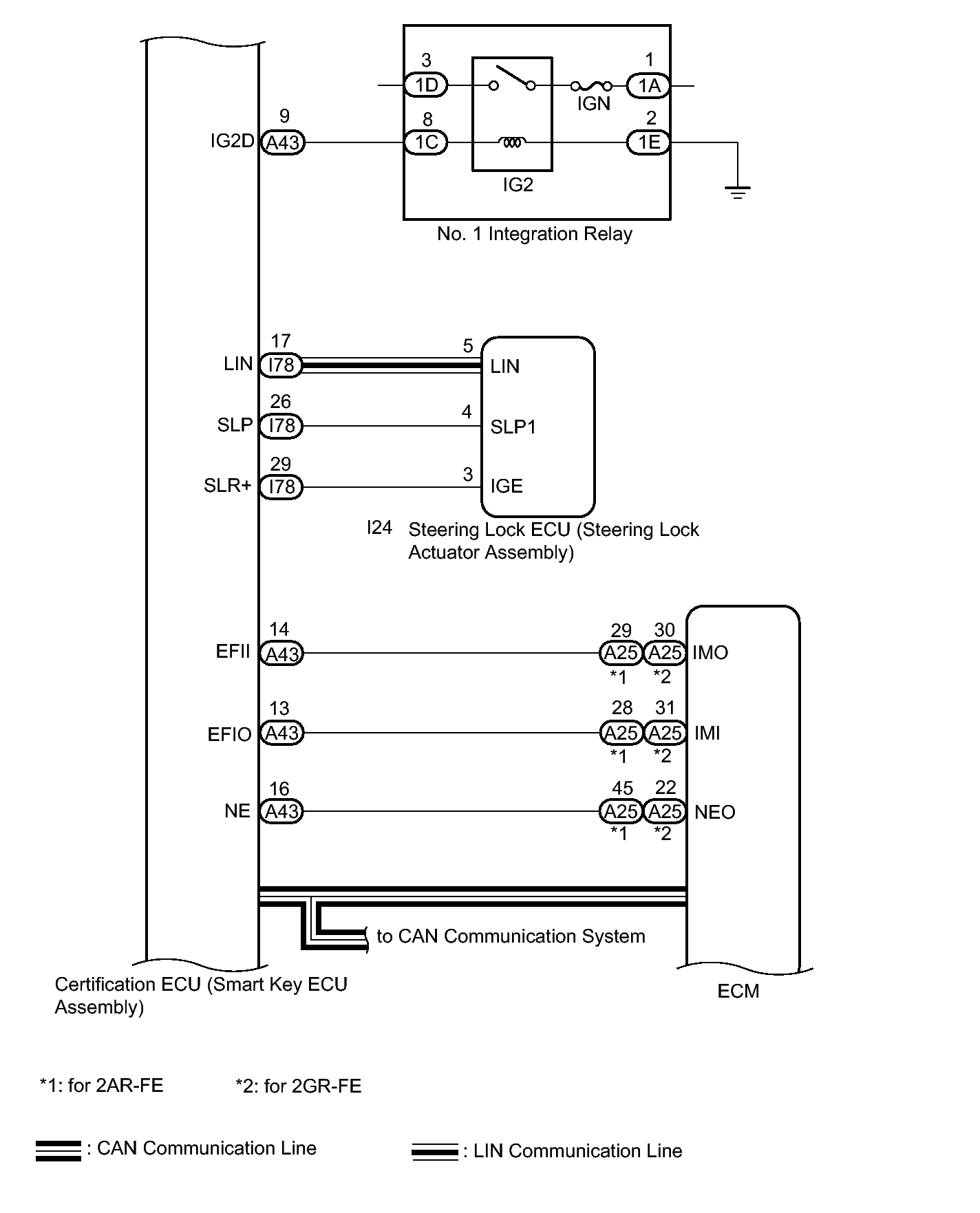
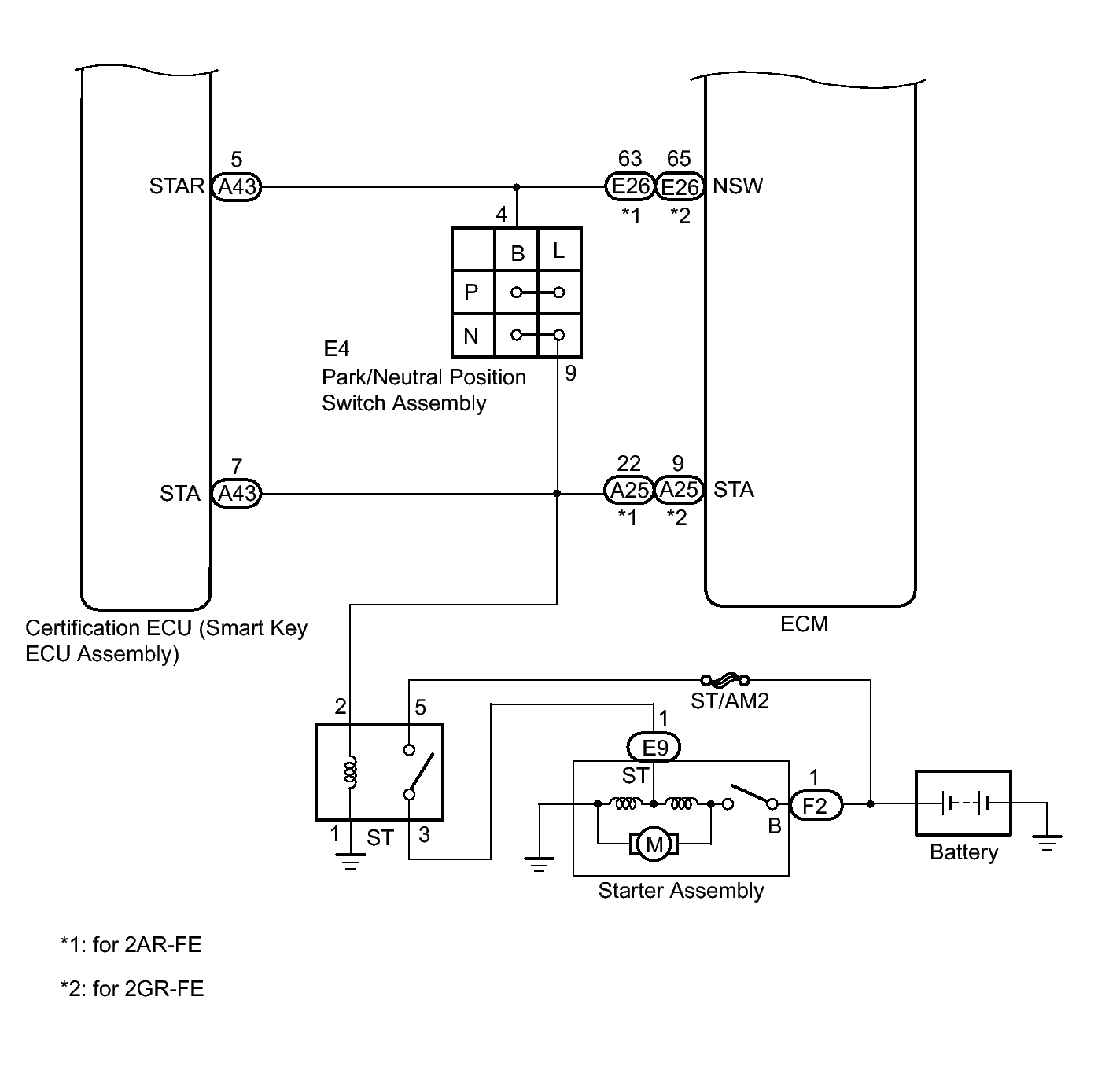
| Certification ECU (smart key ECU assembly) |
- Changes the power source mode by operating the ACC and IG relays.
- Controls starting by operating the starter relay.
- Performs key verification.
- Controls the electrical key antenna (outside), electrical key antenna (indoor) and door lock/unlock sensor.
- Outputs smart entry door lock/unlock commands.
- Outputs steering lock actuator assembly lock/unlock command signals.
- Outputs immobiliser set/unset commands.
- Forms the smart entry detection area.
- Records codes for smart verification.
|
| ECM |
- Outputs a signal indicating that the engine has started to the certification ECU (smart key ECU assembly) when starting the engine.
|
| Steering lock ECU (steering lock actuator assembly) |
- Receives command signals from the certification ECU (smart key ECU assembly) and activates the steering lock actuator assembly.
- Records codes for smart verification.
|
| Combination meter assembly |
- Operates various warnings (messages on the multi-information display, sounding of the buzzer in the combination meter, blinking or illumination of the smart warning light) according to the command signals from the certification ECU (smart key ECU assembly).
- Displays information or operates LED when the smart key system has a malfunction.
- Outputs a vehicle speed signal to the main body ECU (multiplex network body ECU).
|
| IG, ACC relay |
Turns on/off according to the certification ECU (smart key ECU assembly) and provides power to each system. |
| Stop light switch assembly |
Detects that the brake pedal has been depressed (switch is on) and outputs a signal to the certification ECU (smart key ECU assembly). |
No. 1 indoor electrical key antenna assembly (front floor)
No. 2 indoor electrical key antenna assembly (rear floor) |
Sends the request code from the certification ECU (smart key ECU assembly) and forms the vehicle interior detection area. |
| Door control receiver |
Receives the smart key system code/wireless code sent from the key and sends it to the certification ECU (smart key ECU assembly). |
| Electrical key transmitter sub-assembly |
Sends the ID code upon receiving a request signal. |