October 30: LEMON manuals on a temporary server, it is slow and having issues, download the manuals you need! Later in November we will switch back to the fast server.
VSA Modulator-Control Unit Removal and Installation: Installation
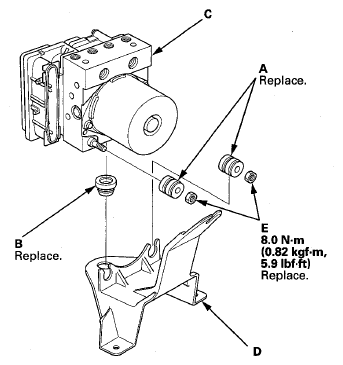
- Install the new rubber dampers (A) and the new grommet (B) to the VSA modulator-control unit (C) (otherwise, unwanted noise and vibration may be transmitted to the vehicle).
 Courtesy of AMERICAN HONDA MOTOR CO., INC.
- Install the VSA modulator-control unit on the bracket (D), then install the new locknuts (E).
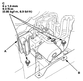
- Install the VSA modulator-control unit (A) with the bracket (B) to the body, then install the VSA modulator-control unit bracket mounting bolts (C).
 Courtesy of AMERICAN HONDA MOTOR CO., INC.
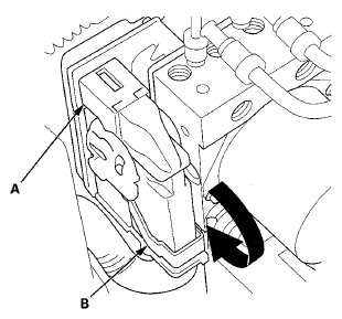
- Align the connecting surface of the VSA modulator-control unit 46P connector (A) to the VSA modulator-control unit.
 Courtesy of AMERICAN HONDA MOTOR CO., INC.
- Pull down the lever (B) of the VSA modulator-control unit 46P connector, then confirm the connector is fully seated.
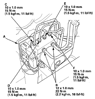
- Connect the 10 mm brake lines and the 12 mm brake lines to the VSA modulator-control unit (A).
NOTE:
Brake lines are connected to the master cylinder (B), the right-front (C), the left-rear (D), the right-rear (E), and the left-front (F) brake systems.
 Courtesy of AMERICAN HONDA MOTOR CO., INC.
- Install the air cleaner (see
AIR CLEANER ELEMENT INSPECTION/REPLACEMENT
).
- Bleed the brake system (see
BRAKE SYSTEM BLEEDING
).
- Do the VSA modulator-control unit update (see VSA MODULATOR-CONTROL UNIT UPDATE
).
- Do the VSA sensor neutral position memorization procedure (see VSA SENSOR NEUTRAL POSITION MEMORIZATION
).
- Do the CMBS initial check (DTC 100) (see
DTC 64: CMBS OPERATION ERROR (EXCESSIVE OPERATION)
).