DTC P0120: Throttle Position (TP) Sensor
- Check Power Supply
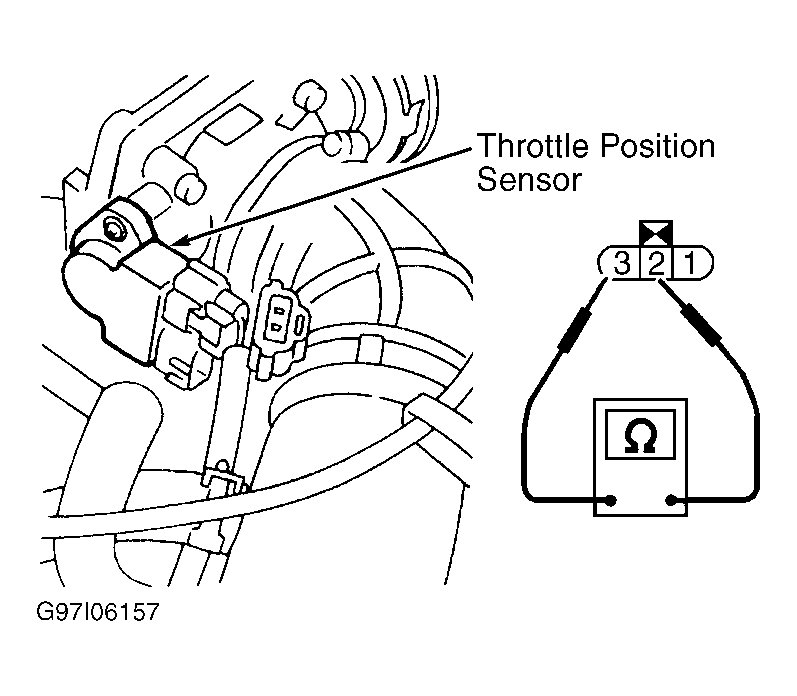
- Turn ignition off. Disconnect TP sensor harness connector. Using a voltmeter, measure voltage between TP sensor harness connector terminal No. 3 (Pink/Black wire) and ground. If voltage is not about 5 volts, repair fault in Pink/Black wire. If voltage is about 5 volts, go to next step.
- Check Ground Circuit
- Turn ignition off. Lossen and retighten engine ground screws. See Figure. Using an ohmmeter, check continuity between TP sensor harness connector terminal No. 1 (Black wire) and engine ground. If no continuity exists, repair open in Black wire. If continuity exists, go to next step.
- Check Input Signal Circuit
- Turn ignition off. Disconnect ECM harness connector. See Figure. Using an ohmmeter, check continuity between ECM harness connect or terminal No. 23 and TP sensor harness connector terminal No. 2 (White wire). If no continuity exists, repair open in White wire. If continuity exists, go to next step.
- Check Component
- Leave TP sensor disconnected. While opening and closing throttle, check resistance across TP sensor connector terminal No. 2 (White wire) and No. 3 (Black wire). See Fig 1. See THROTTLE POSITION SENSOR RESISTANCE table. If resistance is not as specified, adjust TP sensor. See ADJUSTMENTS
article. If resistance is still not as specified after adjustment, replace TP sensor.
THROTTLE POSITION SENSOR RESISTANCE
| Throttle Position |
Ohms |
| Fully Closed |
About 500 |
| Partially Opened |
500-4000 |
| Fully Open |
About 4000 |
 Courtesy of NISSAN MOTOR CO., U.S.A.