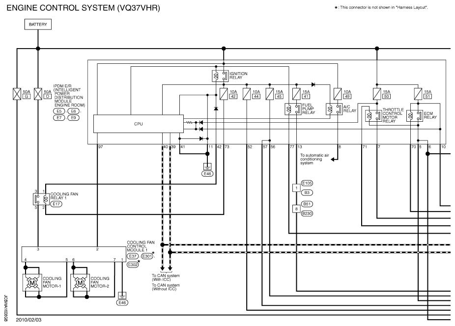
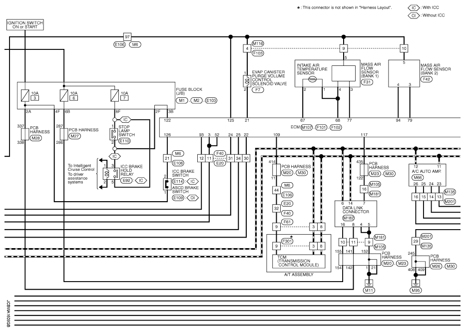
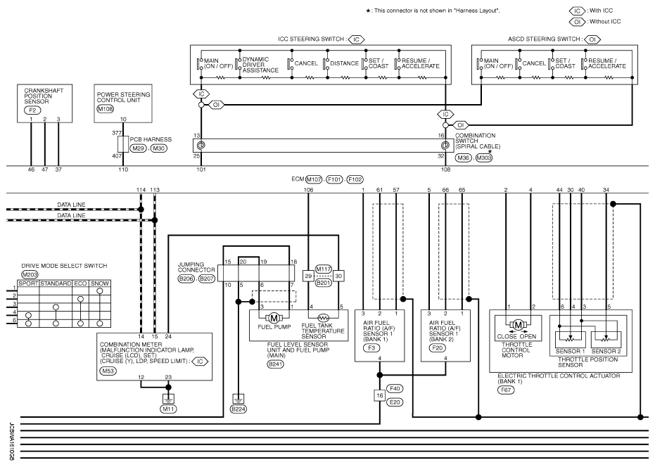
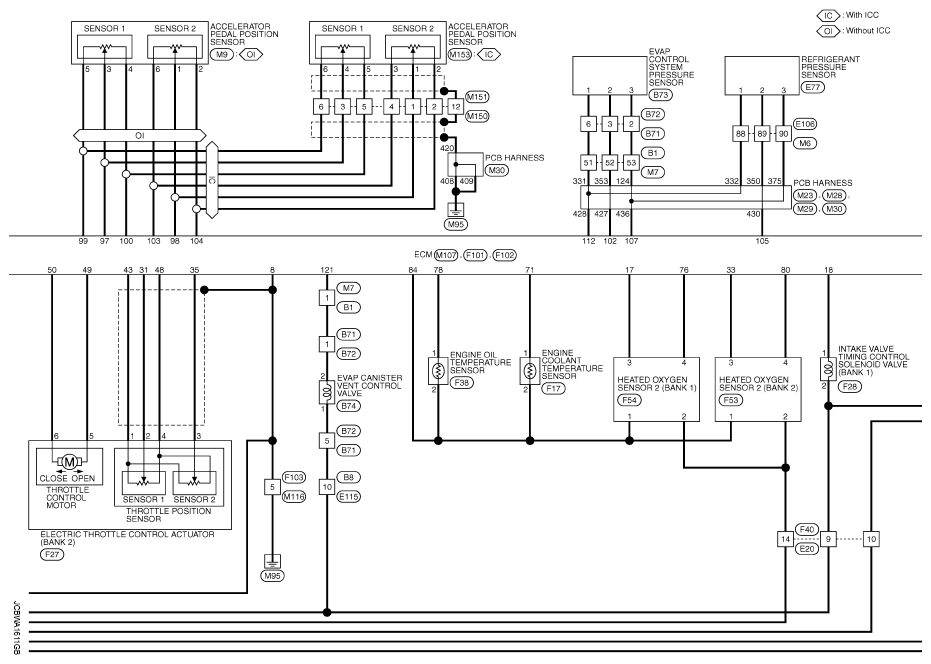
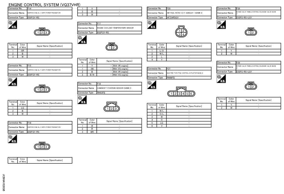
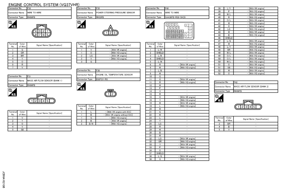
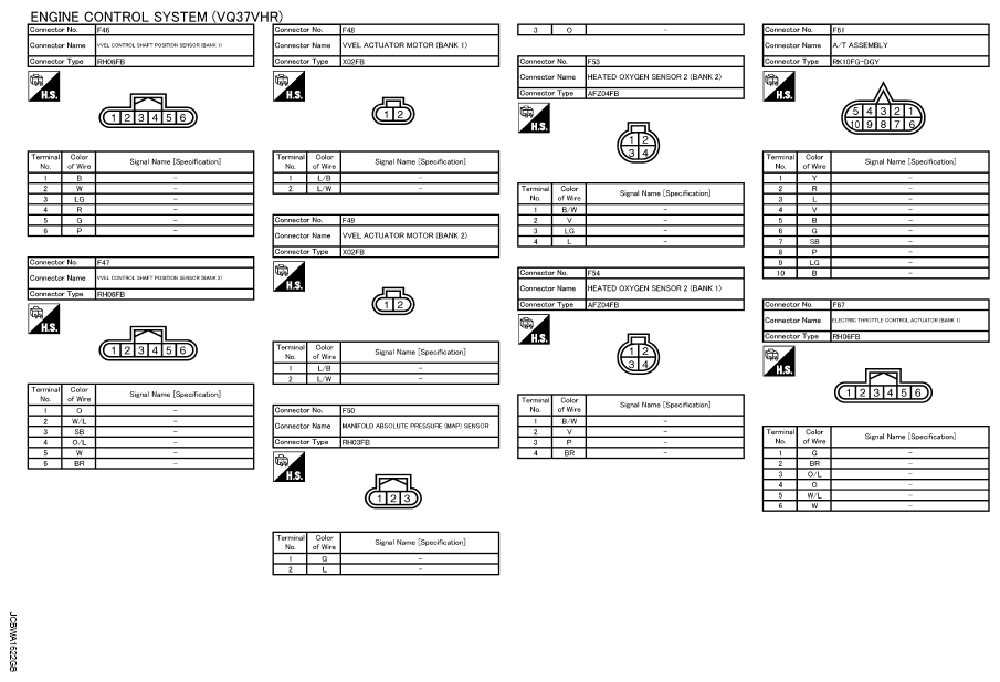
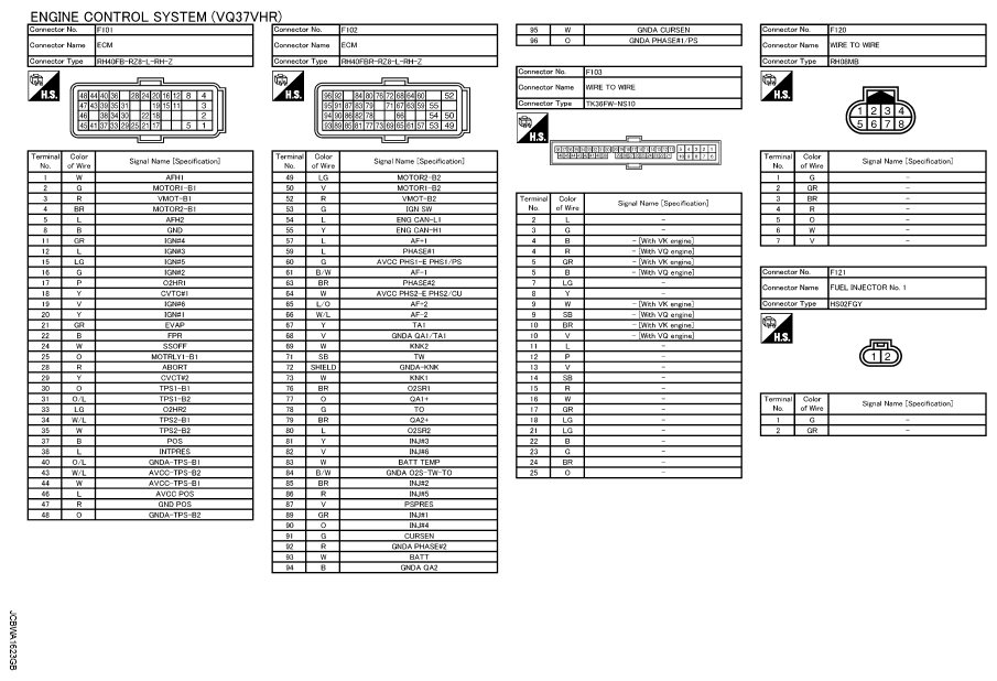
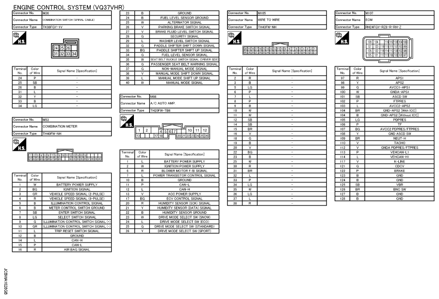
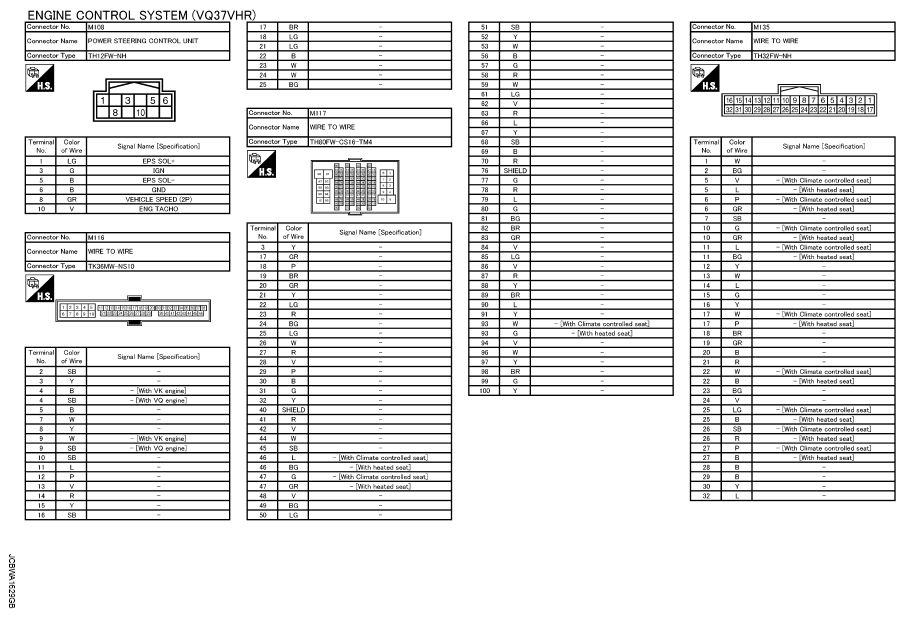
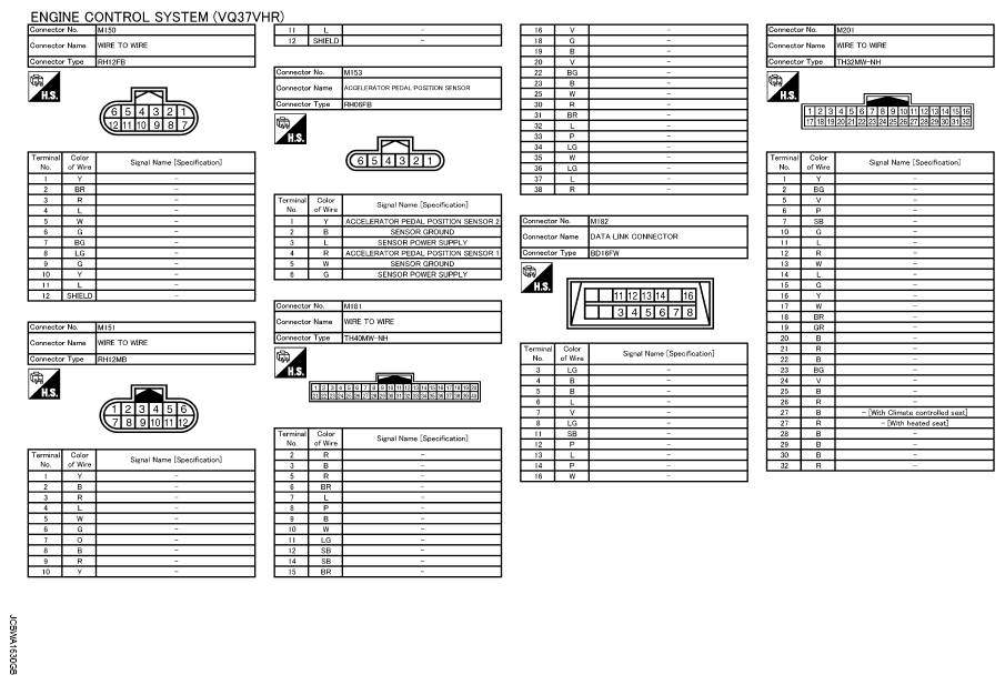
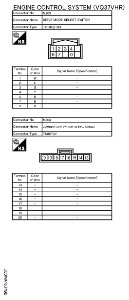
Engine Control System: Wiring Diagram
WARNING: This page is about a different car, the 2011 Infiniti M37. However, it is still accessible from the selected car via links, so may be relevant.
 Courtesy of NISSAN MOTOR CO., U.S.A.
 Courtesy of NISSAN MOTOR CO., U.S.A.
 Courtesy of NISSAN MOTOR CO., U.S.A.
 Courtesy of NISSAN MOTOR CO., U.S.A.
 Courtesy of NISSAN MOTOR CO., U.S.A.
 Courtesy of NISSAN MOTOR CO., U.S.A.
 Courtesy of NISSAN MOTOR CO., U.S.A.
 Courtesy of NISSAN MOTOR CO., U.S.A.
 Courtesy of NISSAN MOTOR CO., U.S.A.
 Courtesy of NISSAN MOTOR CO., U.S.A.
 Courtesy of NISSAN MOTOR CO., U.S.A.
 Courtesy of NISSAN MOTOR CO., U.S.A.
 Courtesy of NISSAN MOTOR CO., U.S.A.
 Courtesy of NISSAN MOTOR CO., U.S.A.
 Courtesy of NISSAN MOTOR CO., U.S.A.
 Courtesy of NISSAN MOTOR CO., U.S.A.
 Courtesy of NISSAN MOTOR CO., U.S.A.
 Courtesy of NISSAN MOTOR CO., U.S.A.
 Courtesy of NISSAN MOTOR CO., U.S.A.
 Courtesy of NISSAN MOTOR CO., U.S.A.
 Courtesy of NISSAN MOTOR CO., U.S.A.
 Courtesy of NISSAN MOTOR CO., U.S.A.
 Courtesy of NISSAN MOTOR CO., U.S.A.
 Courtesy of NISSAN MOTOR CO., U.S.A.