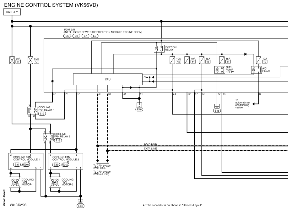
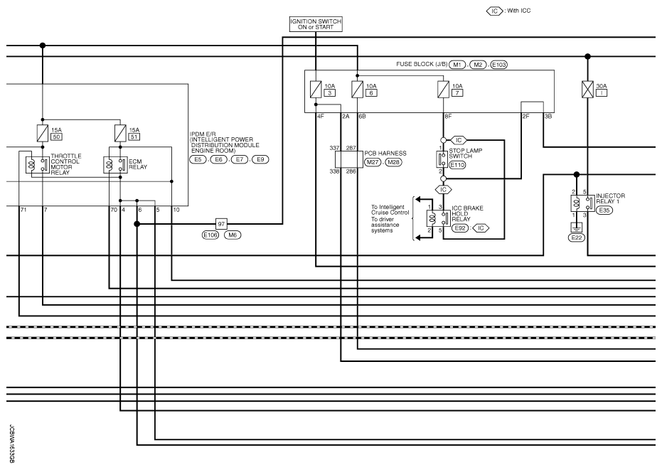
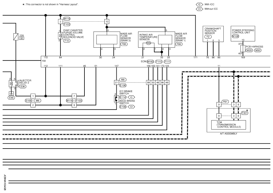
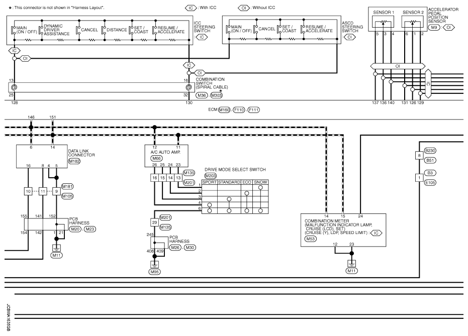
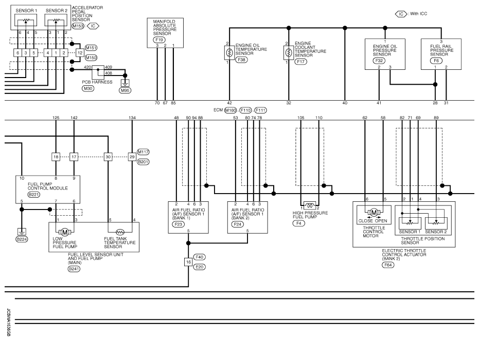
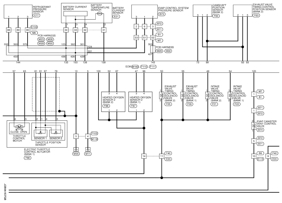
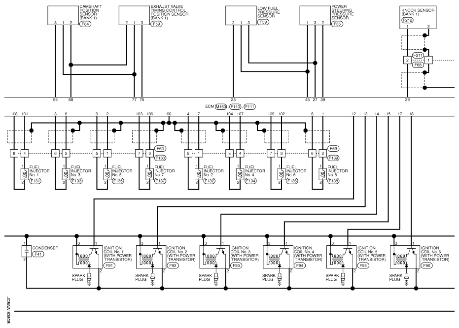
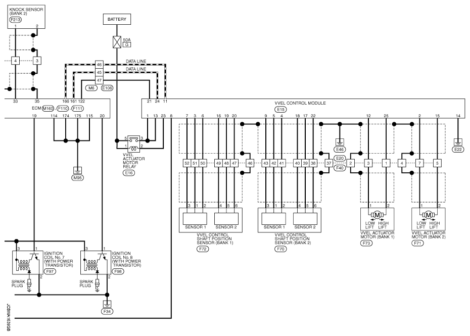
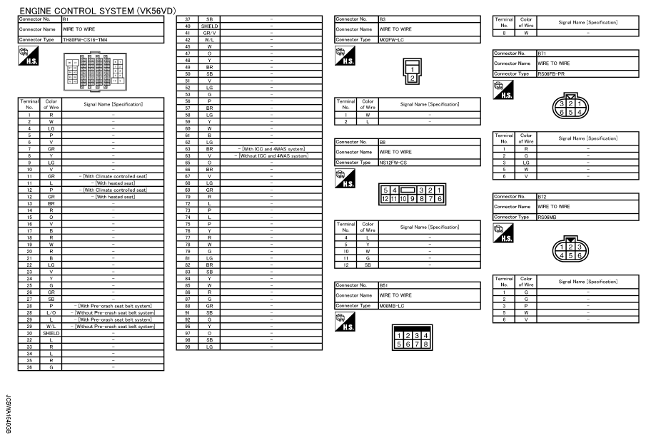
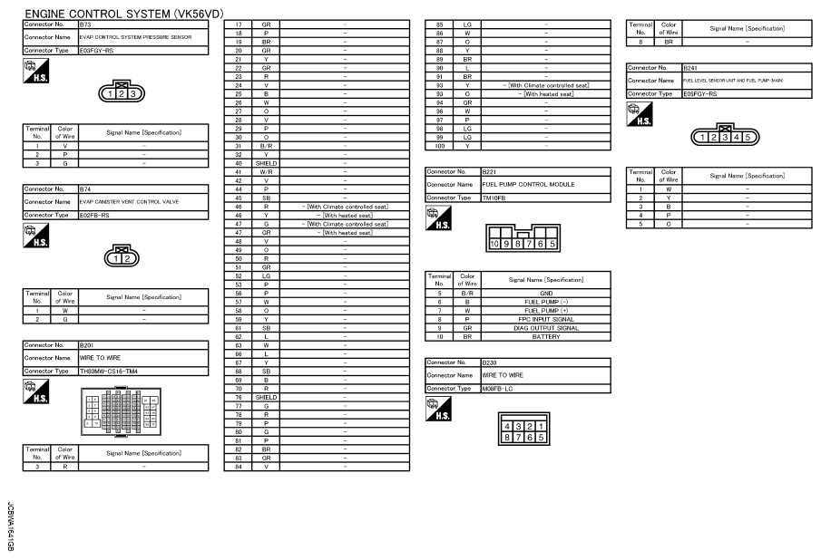
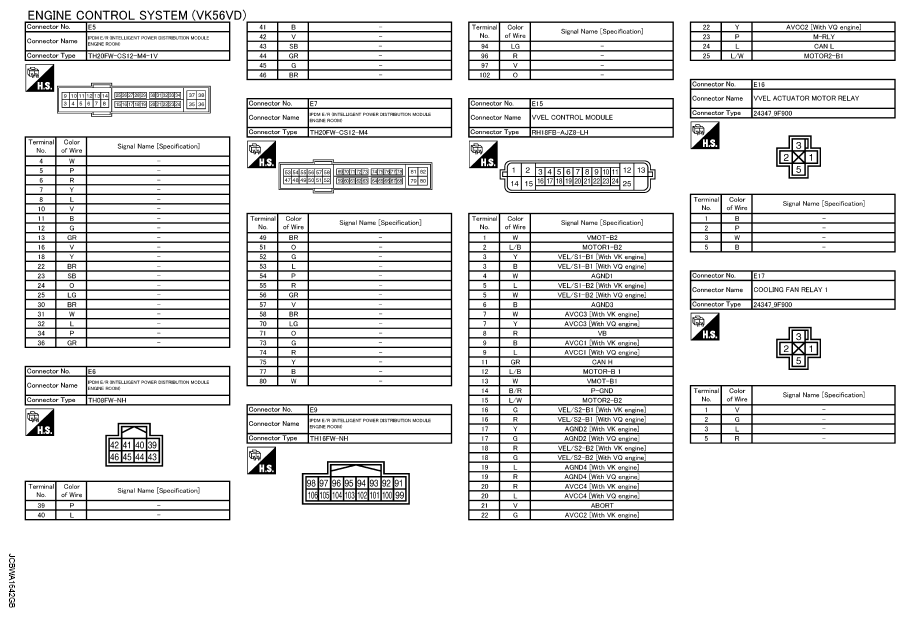
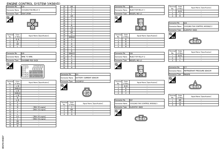
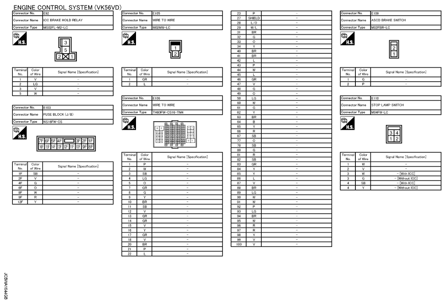
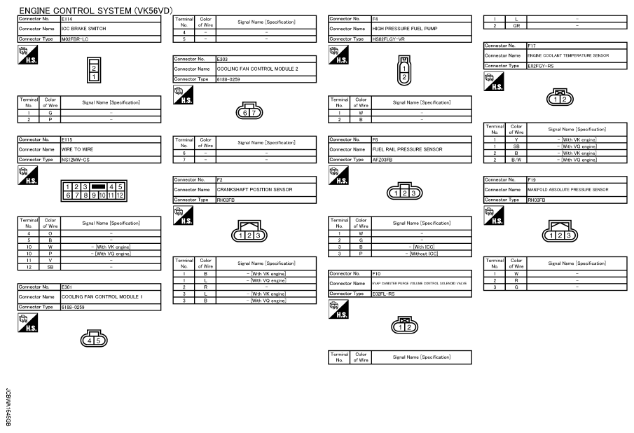
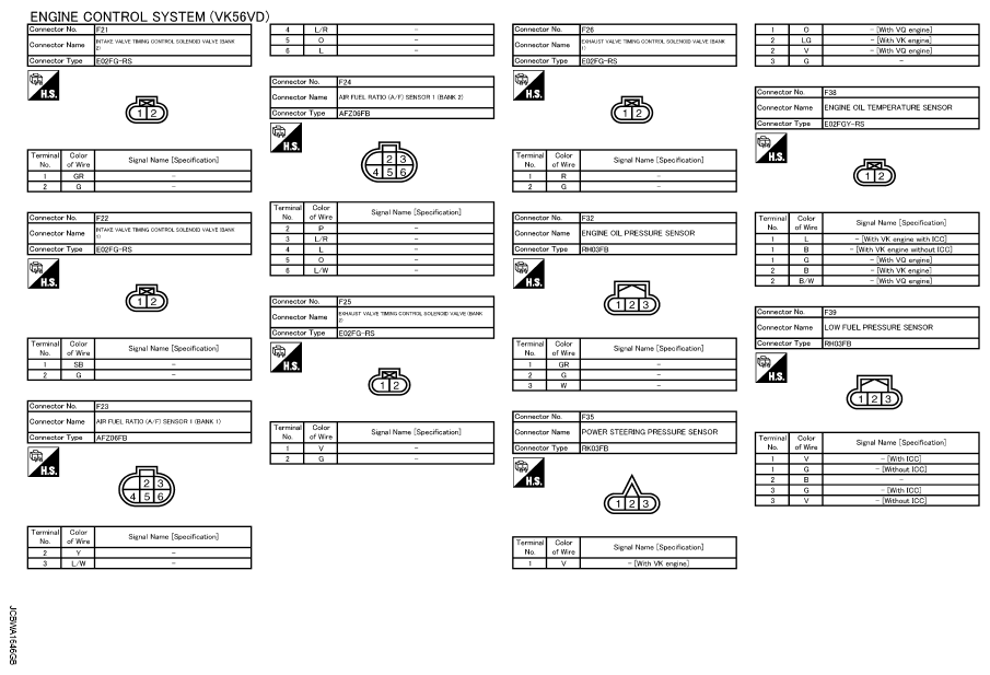
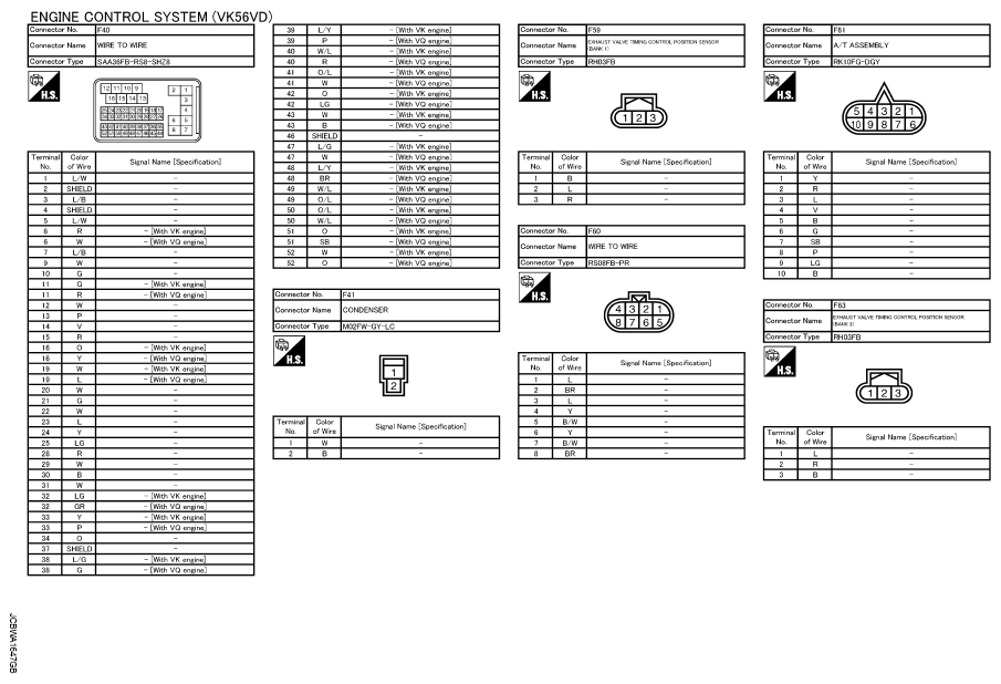
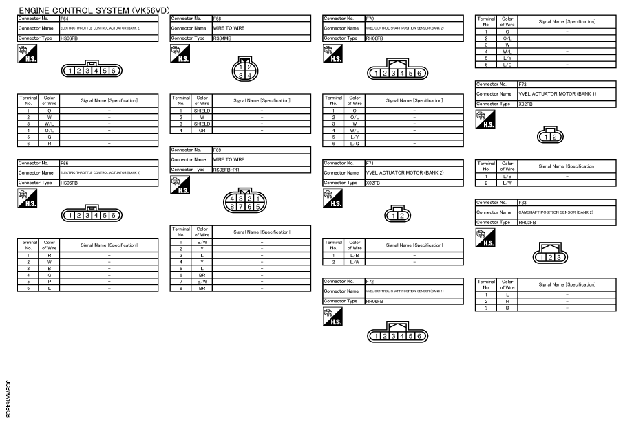
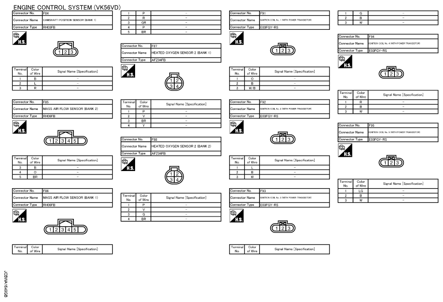
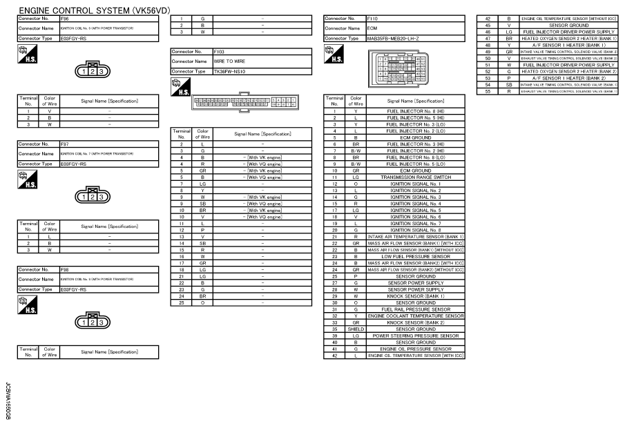
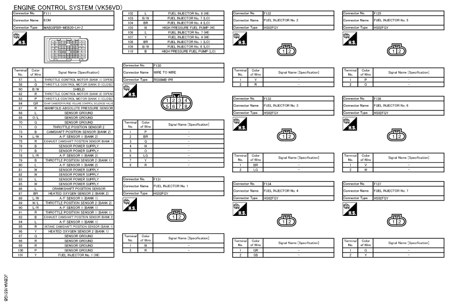
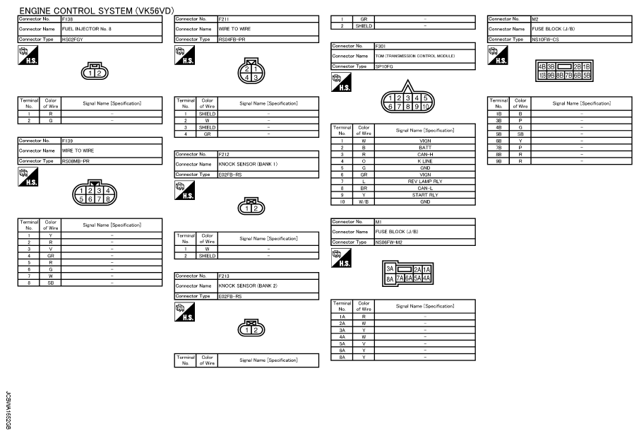
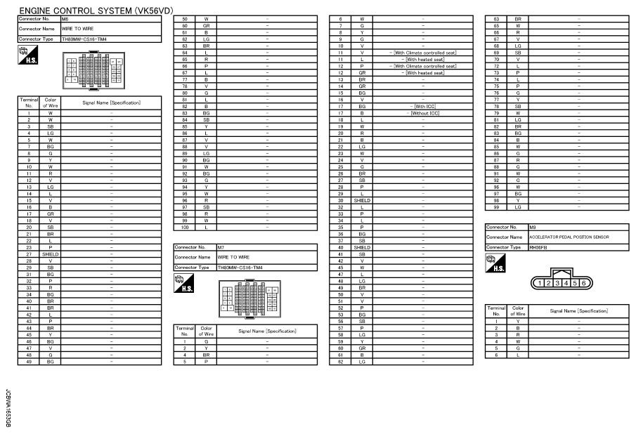
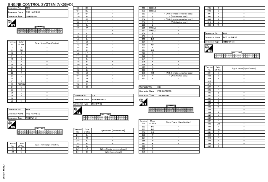
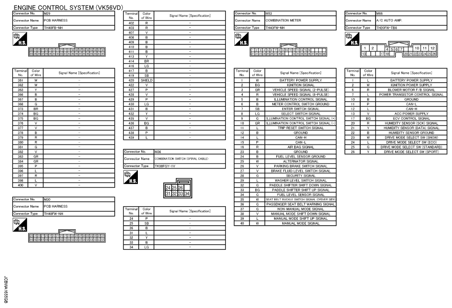
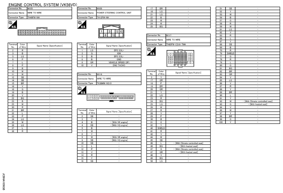
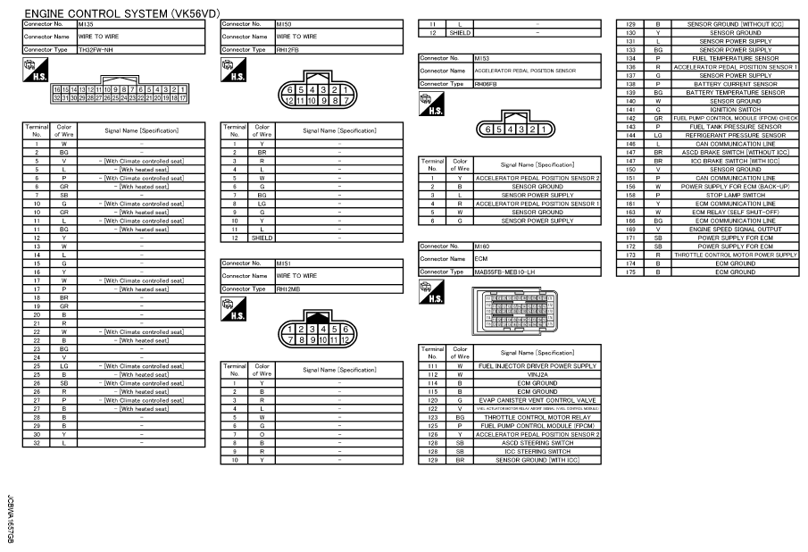
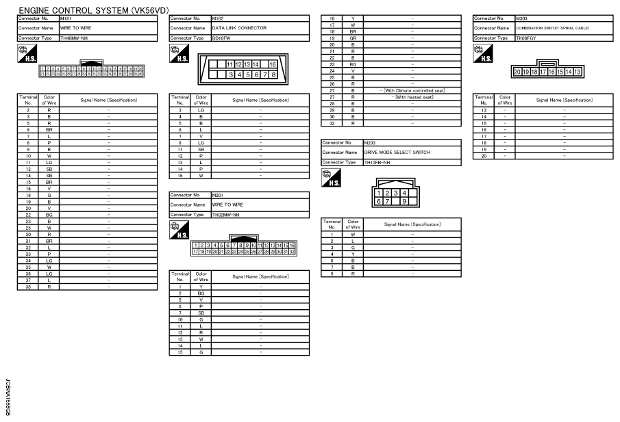
Engine Control System: Wiring Diagram
 Courtesy of NISSAN MOTOR CO., U.S.A.
 Courtesy of NISSAN MOTOR CO., U.S.A.
 Courtesy of NISSAN MOTOR CO., U.S.A.
 Courtesy of NISSAN MOTOR CO., U.S.A.
 Courtesy of NISSAN MOTOR CO., U.S.A.
 Courtesy of NISSAN MOTOR CO., U.S.A.
 Courtesy of NISSAN MOTOR CO., U.S.A.
 Courtesy of NISSAN MOTOR CO., U.S.A.
 Courtesy of NISSAN MOTOR CO., U.S.A.
 Courtesy of NISSAN MOTOR CO., U.S.A.
 Courtesy of NISSAN MOTOR CO., U.S.A.
 Courtesy of NISSAN MOTOR CO., U.S.A.
 Courtesy of NISSAN MOTOR CO., U.S.A.
 Courtesy of NISSAN MOTOR CO., U.S.A.
 Courtesy of NISSAN MOTOR CO., U.S.A.
 Courtesy of NISSAN MOTOR CO., U.S.A.
 Courtesy of NISSAN MOTOR CO., U.S.A.
 Courtesy of NISSAN MOTOR CO., U.S.A.
 Courtesy of NISSAN MOTOR CO., U.S.A.
 Courtesy of NISSAN MOTOR CO., U.S.A.
 Courtesy of NISSAN MOTOR CO., U.S.A.
 Courtesy of NISSAN MOTOR CO., U.S.A.
 Courtesy of NISSAN MOTOR CO., U.S.A.
 Courtesy of NISSAN MOTOR CO., U.S.A.
 Courtesy of NISSAN MOTOR CO., U.S.A.
 Courtesy of NISSAN MOTOR CO., U.S.A.
 Courtesy of NISSAN MOTOR CO., U.S.A.