Installation Procedure
- Remove the transmission from the engine. Refer to TRANSMISSION REPLACEMENT (AWD, LHU/A20NFT)
or TRANSMISSION REPLACEMENT (FWD, LHU/A20NFT)
.
- Position a second floor crane to the transmission lift brackets and raise the floor crane to partially support the transmission.
- Install two transmission lift brackets to the transmission housing.
- Install the starter. Refer to STARTER REPLACEMENT (LHU/A20NFT)
.
- Install the transmission front mount fasteners from the drivetrain and front suspension frame. Refer to TRANSMISSION FRONT MOUNT REPLACEMENT
.
- Install the transmission rear mount fasteners from the drivetrain and front suspension frame. Refer to TRANSMISSION REAR MOUNT REPLACEMENT
.
- Install the engine and the transmission from the drivetrain and front suspension frame.
- Connect a floor crane to the engine lift brackets and raise the floor crane to partially support the engine.
- Install both front wheel drive shafts from the transmission. Refer to FRONT WHEEL DRIVE SHAFT REPLACEMENT - RIGHT SIDE (GNB)
or FRONT WHEEL DRIVE SHAFT REPLACEMENT - RIGHT SIDE (PETROL)
and FRONT WHEEL DRIVE SHAFT REPLACEMENT - LEFT SIDE (GNA)
or FRONT WHEEL DRIVE SHAFT REPLACEMENT - LEFT SIDE (GNB)
.
- Install the engine cooling module from the drivetrain and front suspension frame.
- Install the engine wiring harness from the radiator.
- Install the engine cooling module wiring harness from the drivetrain and front suspension frame.
- Install the radiator outlet hose. Refer to RADIATOR OUTLET HOSE REPLACEMENT (LHU/A20NFT)
.
- Install the radiator inlet hose. Refer to RADIATOR INLET HOSE REPLACEMENT (LHU/A20NFT)
.
- Install the charge air cooler inlet air hose and the charge air cooler outlet hose from the charge air cooler. Refer to CHARGE AIR COOLER RADIATOR REPLACEMENT (LHU/A20NFT)
.
- Install the power steering return hose to the power steering pump. Refer to POWER STEERING RETURN HOSE REPLACEMENT (L4)
.
- Install the power steering pressure pipe/hose to the power steering pump. Refer to POWER STEERING PRESSURE PIPE/HOSE REPLACEMENT (L4)
.
- With the aid of an assistant, lower the table or raise the vehicle to remove the engine, transmission, front frame and front suspension assembly from the vehicle.
- Install the front suspension frame fasteners. Refer to DRIVETRAIN AND FRONT SUSPENSION FRAME INSULATOR REPLACEMENT
.
- Raise the lift table or lower the vehicle to support the frame, engine and transmission.
- Remove the CH-49289
tool. Refer to ENGINE SUPPORT FIXTURE (REAR SIDE) or ENGINE SUPPORT FIXTURE (FRONT SIDE) or ENGINE SUPPORT FIXTURE (MOUNTING ENGINE/TRANSMISSION) or ENGINE SUPPORT FIXTURE (CENTERING ADAPTER) or ENGINE SUPPORT FIXTURE (ENGINE BRIDGE, RETAINER FRAME) .
- Raise the vehicle.
- Install the transmission mount fasteners. Refer to TRANSMISSION MOUNT REPLACEMENT - LEFT SIDE
.
- Install the engine mount bracket to the engine mount support. Refer to ENGINE MOUNT BRACKET REPLACEMENT .
- Lower the vehicle.
- Install the powertrain lift/support table.
- Remove the CH-49290
tool. Refer to ENGINE SUPPORT FIXTURE (REAR SIDE) or ENGINE SUPPORT FIXTURE (FRONT SIDE) or ENGINE SUPPORT FIXTURE (MOUNTING ENGINE/TRANSMISSION) or ENGINE SUPPORT FIXTURE (CENTERING ADAPTER) or ENGINE SUPPORT FIXTURE (ENGINE BRIDGE, RETAINER FRAME) .
- Position a suitable powertrain or engine lift table below the frame, engine and transmission.
- Raise the vehicle enough to place a suitable lift table under the engine, transmission, front frame and front suspension assembly.
- Install the engine shield from the front suspension frame.
- If available install both drivetrain and front suspension frame transmission protectors.
- Install the exhaust front pipe. Refer to EXHAUST FRONT PIPE REPLACEMENT .
- Install the propeller shaft. Refer to PROPELLER SHAFT REPLACEMENT
.
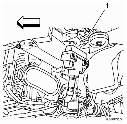
- Position and secure the relay box to the engine.
- Install the relay box (1).
 Courtesy of SAAB-SCANIA OF AMERICA, INC.
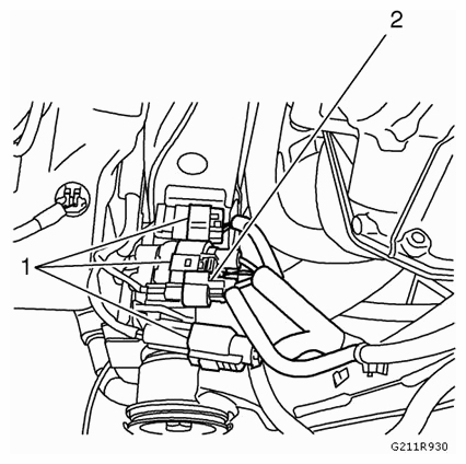
- Connect the power steering wiring harness connector (2).
 Courtesy of SAAB-SCANIA OF AMERICA, INC.
- Connect the engine coolant fan motor wiring harness connectors (1).
- Connect both front wheel speed sensor electrical connectors. Position and secure both wiring harnesses to the vehicle. Refer to FRONT WHEEL SPEED SENSOR REPLACEMENT (GNA)
or FRONT WHEEL SPEED SENSOR REPLACEMENT (GNB)
.
- Install both front wheel drive shafts from both front wheel bearings and hubs. Refer to FRONT WHEEL BEARING AND HUB REPLACEMENT (GNA)
or FRONT WHEEL BEARING AND HUB REPLACEMENT (GNB)
.
- Install both steering knuckles to both front lower control arms. Refer to STEERING KNUCKLE REPLACEMENT (GNA)
or STEERING KNUCKLE REPLACEMENT (GNB)
.
- Install the steering linkage outer tie rod fasteners. Refer to STEERING LINKAGE OUTER TIE ROD REPLACEMENT
.
- Install the stabilizer shaft link fasteners. Refer to STABILIZER SHAFT LINK REPLACEMENT (GNA)
or STABILIZER SHAFT LINK REPLACEMENT (GNB)
.
- Install the front wheel drive shaft fasteners. Refer to FRONT WHEEL DRIVE SHAFT REPLACEMENT - RIGHT SIDE (GNB)
or FRONT WHEEL DRIVE SHAFT REPLACEMENT - RIGHT SIDE (PETROL)
and FRONT WHEEL DRIVE SHAFT REPLACEMENT - LEFT SIDE (GNA)
or FRONT WHEEL DRIVE SHAFT REPLACEMENT - LEFT SIDE (GNB)
.
- Install the front wheels. Refer to TIRE AND WHEEL REMOVAL AND INSTALLATION
.
- Raise and support the vehicle. Refer to LIFTING AND JACKING THE VEHICLE
.
- Install the air conditioning compressor and the condenser hose and the air conditioning evaporator hose. Refer to AIR CONDITIONING COMPRESSOR AND CONDENSER HOSE REPLACEMENT (LHU/A20NFT)
and AIR CONDITIONING EVAPORATOR HOSE ASSEMBLY REPLACEMENT (LHU/A20NFT)
.
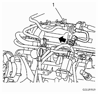
- Connect the evaporative pipe quick connector (1).
 Courtesy of SAAB-SCANIA OF AMERICA, INC.
- Plug the fuel feed pipe and cap the fuel injection fuel rail to prevent fuel loss or contamination.
- Install the fuel feed front pipe. Refer to FUEL FEED PIPE REPLACEMENT (METAL)
or FUEL FEED PIPE REPLACEMENT (PLASTIC)
.
- Install the heater inlet hose and the heater outlet hose from the heater core. Refer to HEATER INLET HOSE REPLACEMENT (LHU/A20NFT)
and HEATER OUTLET HOSE REPLACEMENT (LHU/A20NFT)
.
- Relieve the fuel system pressure. Refer to FUEL PRESSURE RELIEF
.
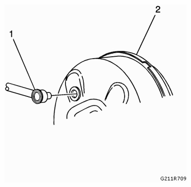
- Install the power brake booster pipe (1) from the power brake booster (2).
 Courtesy of SAAB-SCANIA OF AMERICA, INC.
- Position and secure the manual transmission shift lever cable to the vehicle.
- Install the manual transmission shift lever cable to the transmission. Refer to RANGE SELECTOR LEVER CABLE REPLACEMENT
.
- Install the engine coolant air bleed hose. Refer to ENGINE COOLANT AIR BLEED HOSE REPLACEMENT (LHU/A20NFT)
.
- Install the radiator surge tank hoses from the radiator surge tank. Refer to RADIATOR SURGE TANK ENGINE HOSE REPLACEMENT
.
- Install the engine wiring harness (1) to the front compartment fuse block housing (2).
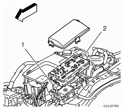 Courtesy of SAAB-SCANIA OF AMERICA, INC.
- Install the engine wiring harness ground connectors (1) from the front end upper tie bar support.
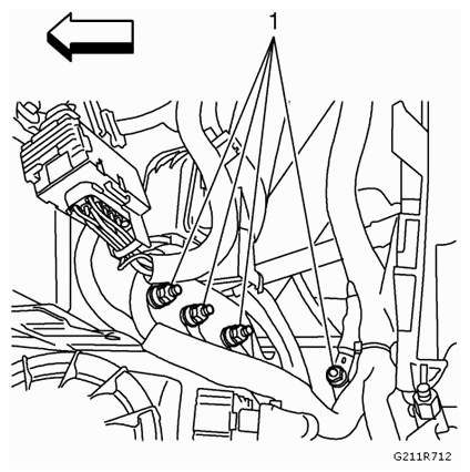 Courtesy of SAAB-SCANIA OF AMERICA, INC.
- Connect the engine wiring harness connectors (1, 2, 3).
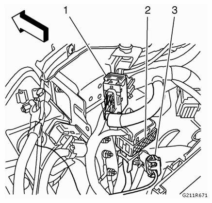 Courtesy of SAAB-SCANIA OF AMERICA, INC.
- Fill the cooling system. Refer to COOLING SYSTEM DRAINING AND FILLING (LHU/A20NFT)
.
- Install the charge air cooler air inlet hose and the charge air cooler air outlet hose. Refer to CHARGE AIR COOLER INLET AIR HOSE REPLACEMENT and CHARGE AIR COOLER OUTLET AIR HOSE REPLACEMENT .
- Install the air cleaner assembly. Refer to AIR CLEANER ASSEMBLY REPLACEMENT
.
- Install the air cleaner outlet duct. Refer to AIR CLEANER OUTLET DUCT REPLACEMENT
.
- Install the battery tray. Refer to BATTERY TRAY REPLACEMENT
.
- Install the engine control module. Refer to ENGINE CONTROL MODULE REPLACEMENT
.
- Evacuate the air conditioning system. Refer to REFRIGERANT RECOVERY AND RECHARGING
.
- Install the engine sight shield. Refer to ENGINE SIGHT SHIELD REPLACEMENT .
- Install the intermediate steering shaft fastener. Refer to INTERMEDIATE STEERING SHAFT REPLACEMENT
.